Together with some friends, I decided earlier this year to particpate in the Carbage run 2025 Winter edition. This is a 6-day journey in winter all the way through Sweden to the polar circle, and back down to Helsinki in a group of roughly 400 cars.
One small catch (you might have guessed it from the name): your car has to be “carbage”. In practice, this means it needs to be at least 20 years old, and with a day value of less than €1000.


This route, including the drive to get there and back from Belgium would mean driving roughly 6000km in just over a week, often in less-than-ideal conditions. In addition, our car will also be judged on originality, which is why this idea popped into my head:

Why not make it self-driving?
What?? How is this even possible?
For those who don’t know: there is this project named openpilot, developed by comma.ai which adds L2 advanced driver assistance features (fancy words for partially self driving like Tesla’s Autopilot) to over 275+ supported car models such as recent Toyotas, Hondas, Hyundais, VWs, … Hell, there’s even support for Tesla’s Model 3/Y!
The key word here is “recent”, which is to say: the cars that are supportable need to have some electronic way of actuating steering, gas and brakes. This is the case in pretty much all modern cars, since stock ADAS features such as lane keeping assists and adaptive cruise control are more and more prevalent.
In these cases, the actuators are usually implemented in the form of Electric Power Steering (EPS), electric brake boosters / ABS pumps and electronic engine control units. These then accept (reasonable) actuation commands over CAN-bus messages from a camera module or similar, which then can be intercepted and replaced by more appropriate commands for openpilot.
Coincidentally, I’ve been working at comma.ai for about 5 years as a hardware engineer, so I am quite familiar with the inner workings of the whole system. A few years ago, I even gave a talk about controlling cars that goes a bit more in depth.
(by the way: we're hiring!)
Back to 1993
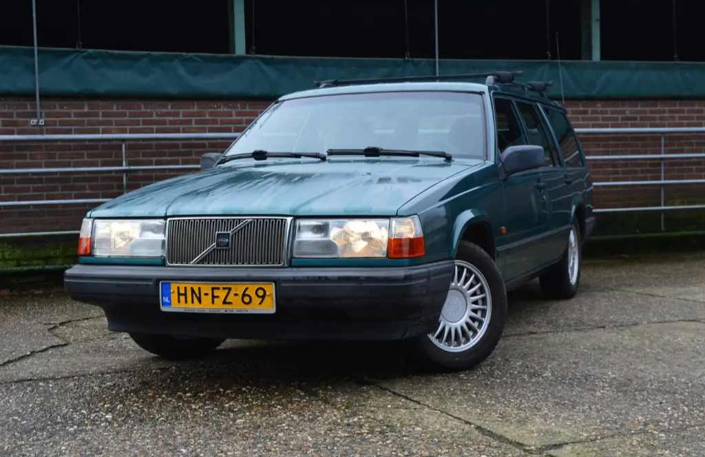
This is the car we bought, sight-unseen at an online auction: a 1993 Volvo 940 Estate. While the state of the paint wouldn’t suggest it, it was actually in surprisingly good condition for a car over 30 years old.
As you can imagine, there are very little electronics in this car: the steering is hydraulic, the accelerator is driven by a cable between the gas pedal and the carburator, and the brake booster is vacuum-based.
Let’s go over these one by one and explain on how we can retrofit the needed actuators:
Steering motor and sensor
Probably the most important actuator needed for staying on the right track (and the one that turned out to be the most complex to adapt mechanically) is for the steering assist. As mentioned, the Volvo is fitted from the factory with a hydraulically powered assist on the steering rack.
To be able to put torque on the wheel electronically, the most feasible option we found is to retrofit an electric power steering actuator / ECU from a 2020 Toyota Corolla. In the Corolla, this motor is mounted on the steering column behind the dashboard, and amplifies the measured driver torque to the output shaft.
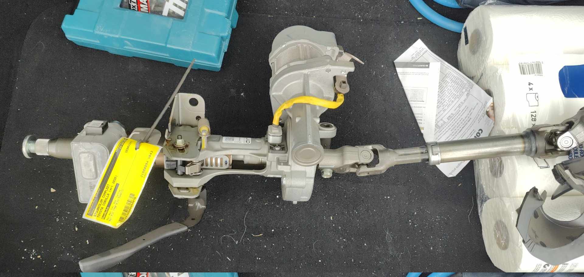 The 2020 Corolla steering rack we got from a junkyard
While the full rack looks quite big, most of it is related to the steering wheel adjustment features, which can be removed for our use-case. To fit it behind the dash, we took out the original straight-axle steering column from the Volvo and fit the EPS inbetween:
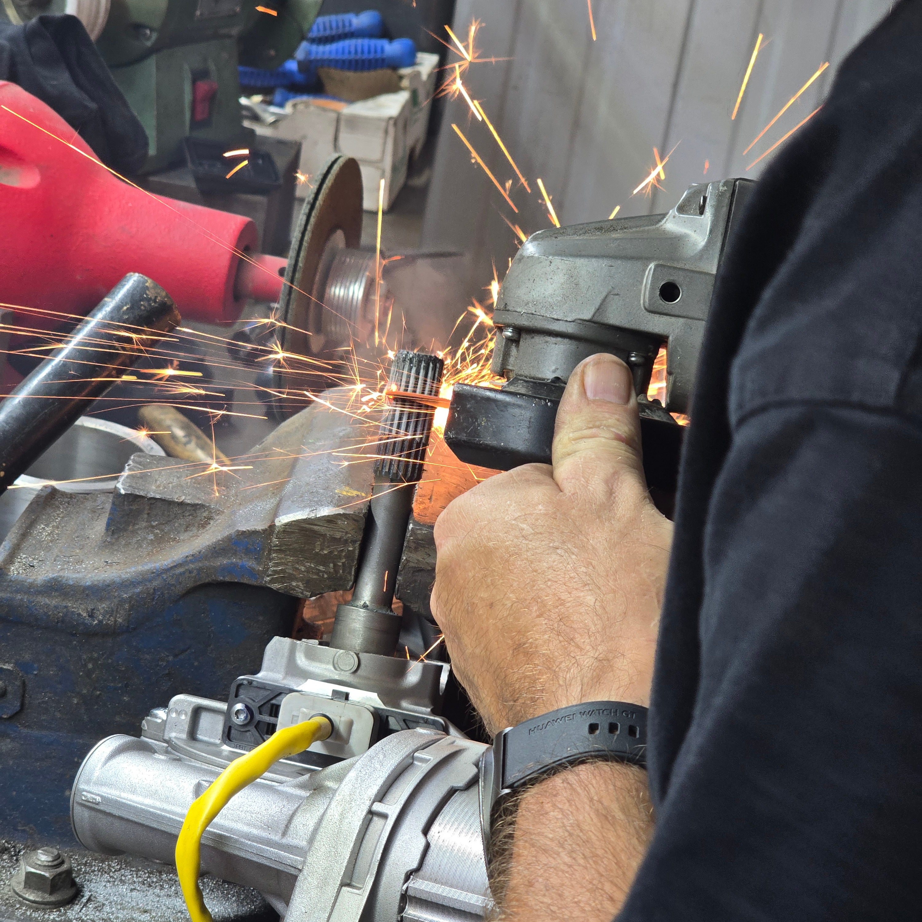
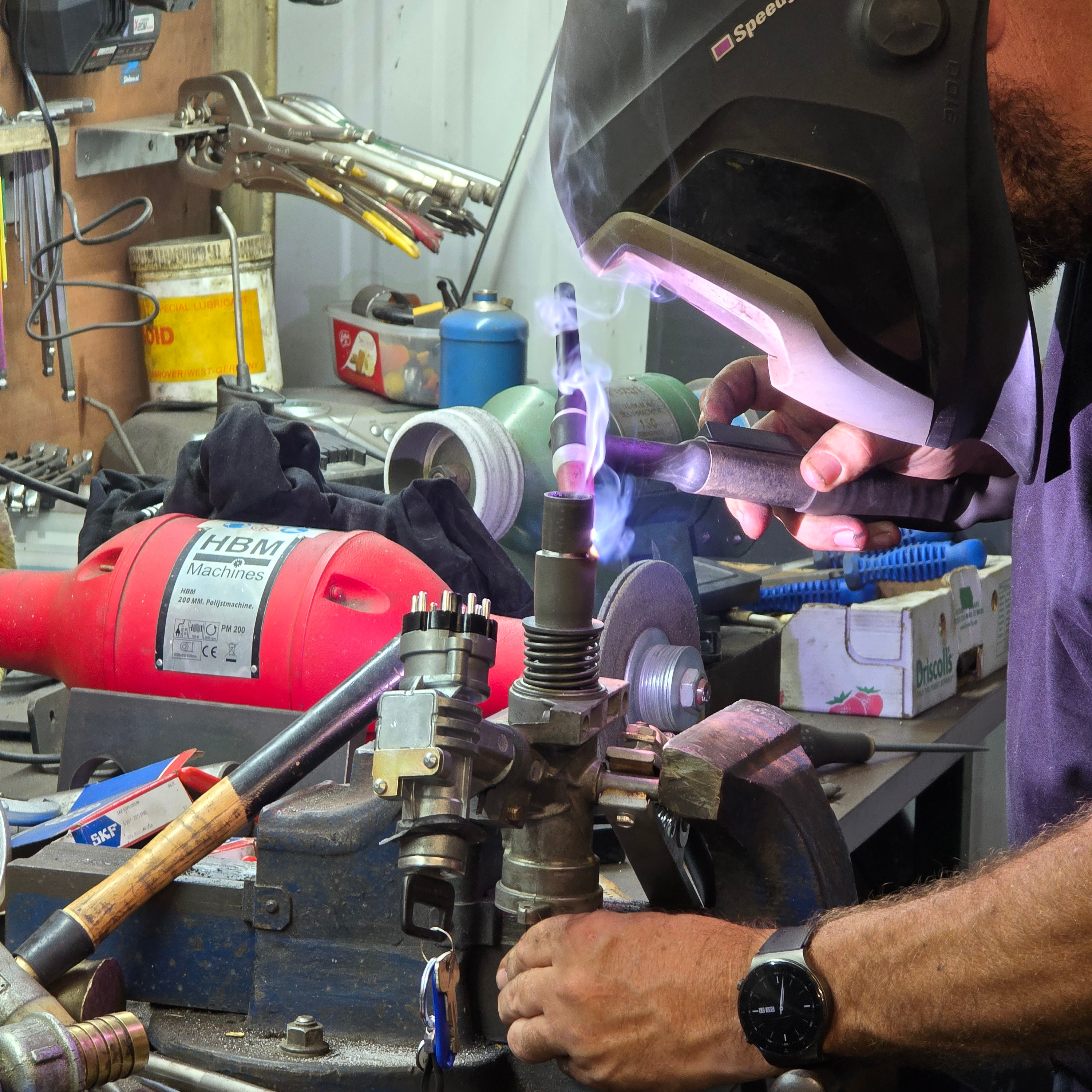 We cut off as much as we could from the Corolla rack and welded the interfacing splines to the top of the original Volvo column (which we also cut in pieces)
With the motor now on the column, we added some extra bracing from the original steering frame to the EPS:
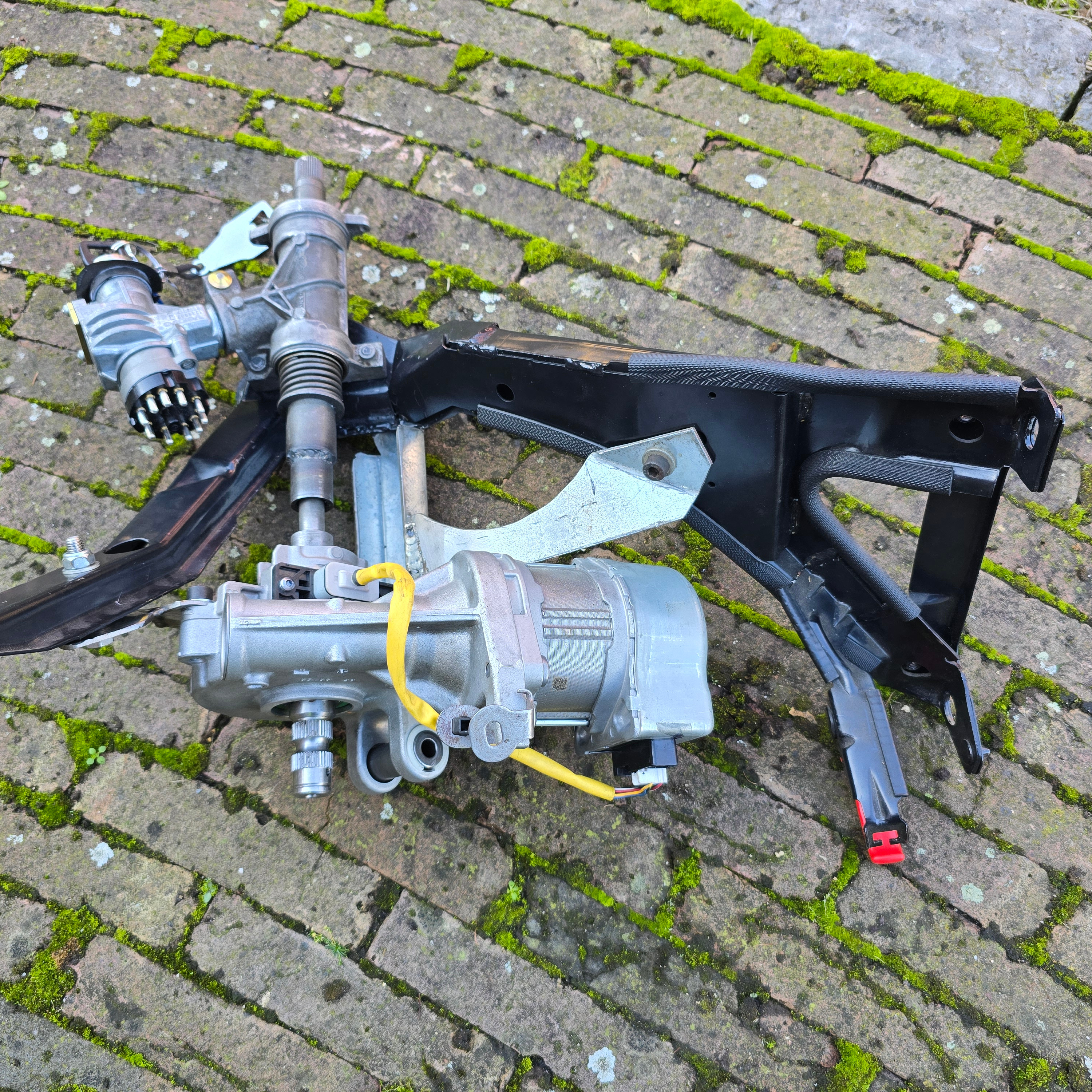
Except for the motor itself, the Corolla also has an exernal steering angle sensor. While the EPS motor has one built-in, it is only used for precise relative angles needed for the inner control loops. The external angle sensor provides it with an absolute angle measurement (zero degrees while the car is moving in a straight line), which is also needed for openpilot’s car controller code.
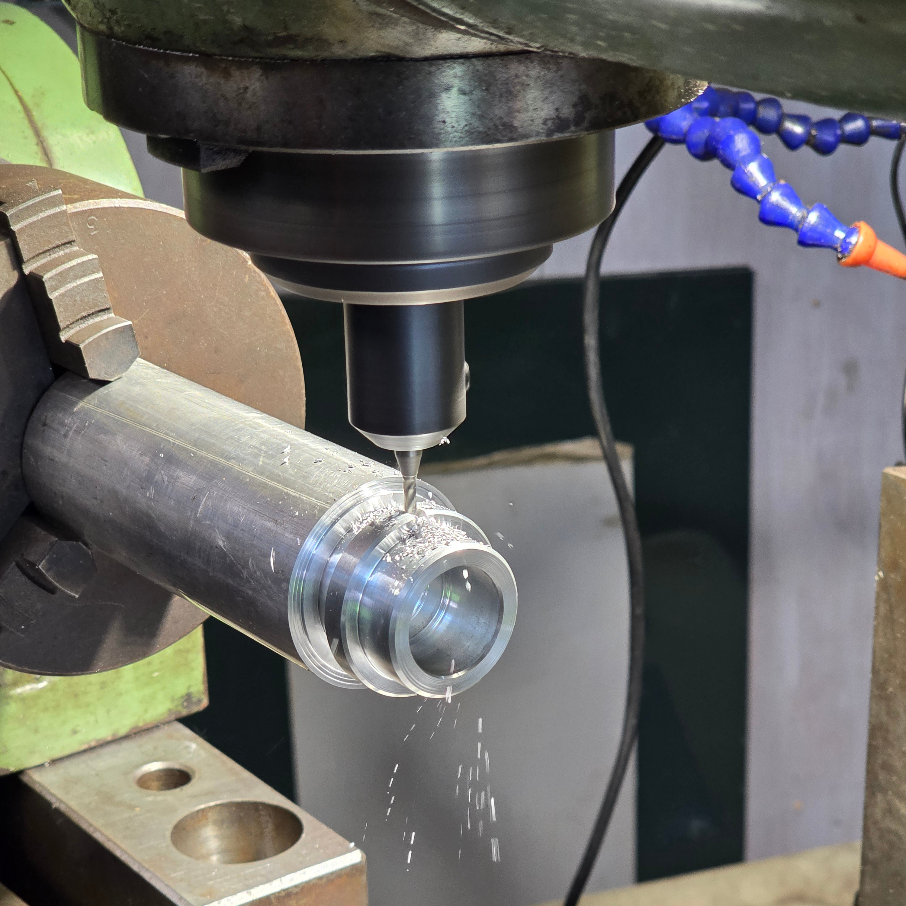
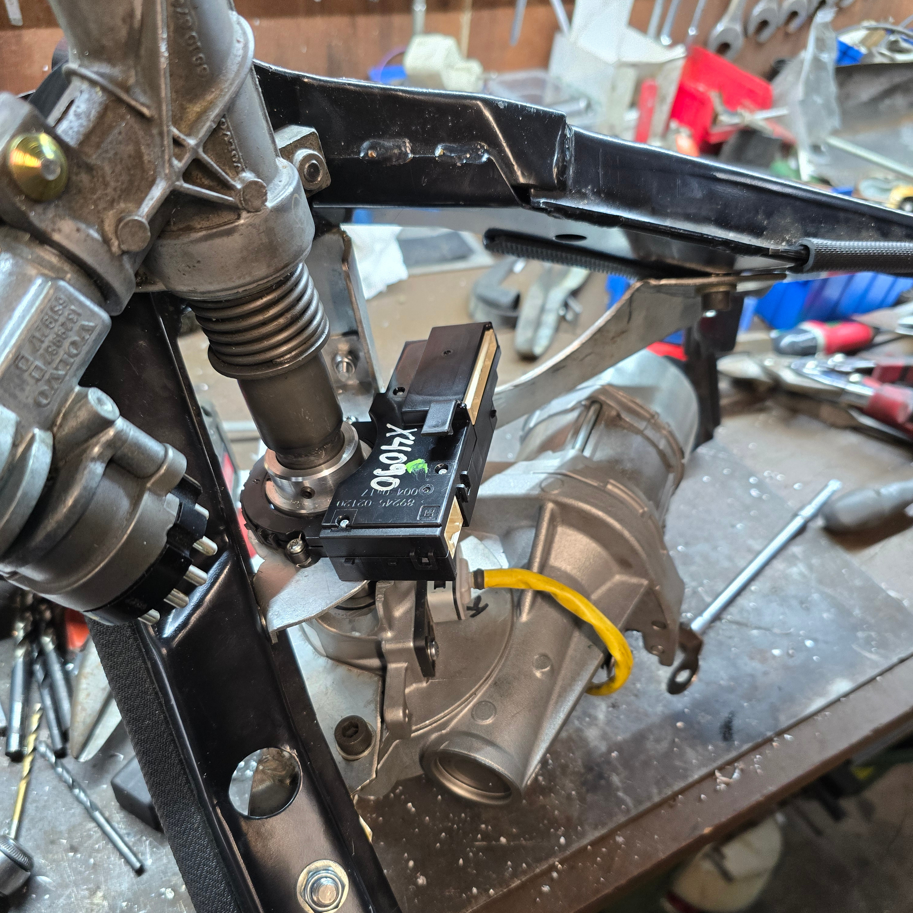 Machining a bushing to connect the angle sensor to the steering column shaft, and the sensor installed.
With both the motor and angle sensors installed in the steering subframe, it can be mounted in the car again. To our surprise, there was enough space under the dash to accomodate all this extra hardware, and no further modifications were necessary to get the dash back in!
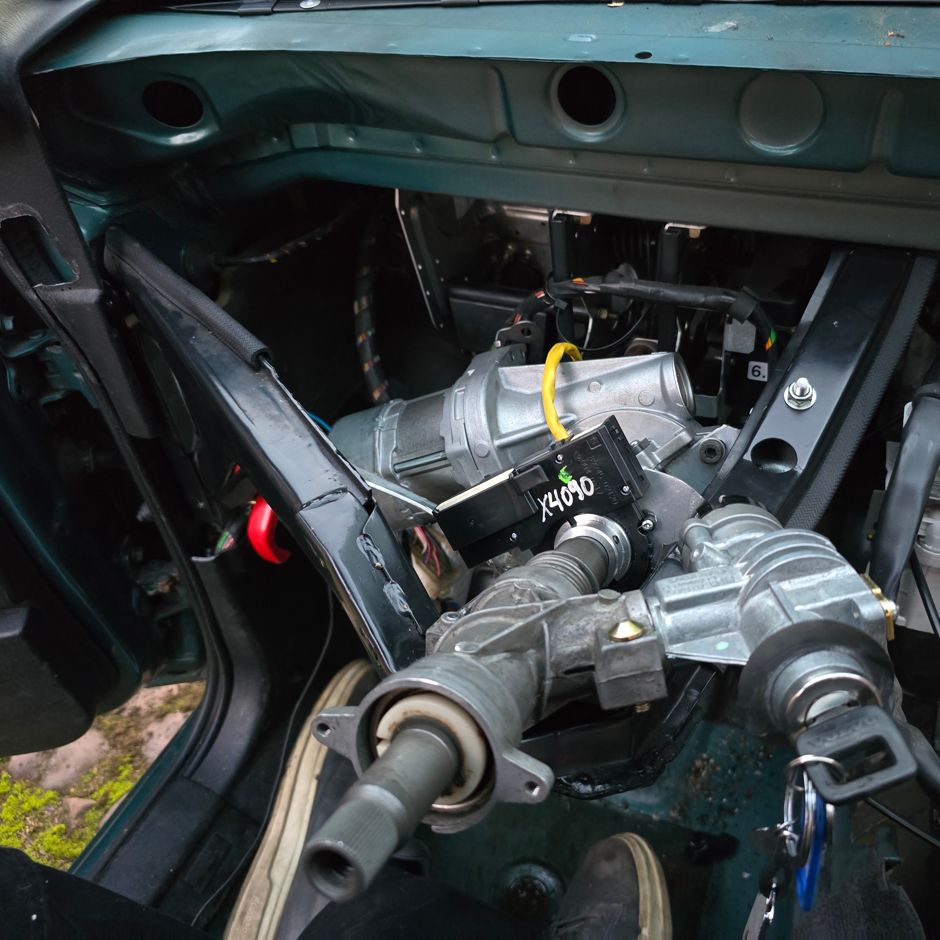
I’ll dive into the wiring a bit more in an upcoming blog post, but in summary: hooking up the motor and angle sensor electrically is very straight-forward. Since you can download the schematics and connector references from Toyota for a small fee, it was easy to figure out that the steering rack only needs GND, constant 12V (fused at 80A!), a 12V “ignition” signal and CAN to the angle sensor.
With just that, the EPS springs to life (likely in limp-mode since it’s missing some Toyota-messages it expects with the current car speed, …) and happily works as if it was in its original car.
What about the original hydraulic steering assist? Don’t you have two systems now?
Good observation. In short: yes.
While you could just disable the hydraulic power assist and just rely on the new electric one, I fear that the steering rack might not be designed to handle the higher amounts of torque it would constantly receive from the EPS during normal driving and might potentially wear out over time.
The steering works just fine with both systems active (it made the steering nice and light too!), but it’s not ideal. One downside of having both assists active is that the car doesn’t have enough self-centering torque to backdrive both systems and center the steering wheel when you let go of the wheel in a curve; It just stays where you put it.
There might be multiple ways to resolve this, although I have not tried yet. For example, it might be possible to reduce the hydraulic pressure in the system, rendering the original assist less powerful.
Brake booster
Probably the most effective feature modern cars offer for reducing driver load in long drives is adaptive cruise control. To be able to follow the car in front of you at a safe distance without manual interventions, the car needs to be able to brake automatically.
As you can guess by now: this is not something the 30-year-old Volvo was set up to do from the factory. Originally, the car’s brakes rely on a simple vacuum-assist system to amplify the pressure the driver puts on the brake pedal, which in turn pushes on the master cylinder.
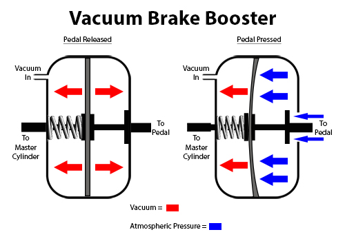 Diagram of a vacuum-assisted braking system (Image source: Summit Racing)
Luckily, modern cars still work in a very similar way. In fact, the system used by Tesla for example is based on the Bosch iBooster, which just replaces the vacuum-assist with a force sensor and an electric motor:
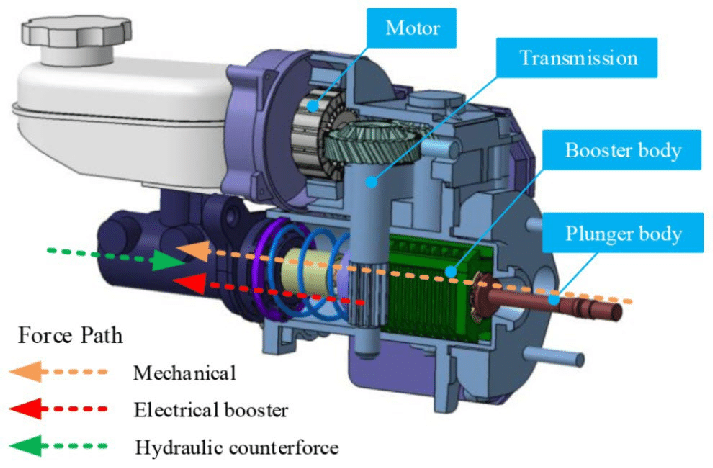 Diagram of the Bosch iBooster (Source)
Unfortunately, it is well-known that these iBoosters are very useful for EV-conversion projects, since this is a way cleaner setup than having to replace the original engine’s vacuum source to get the original booster to work. It’s also widely known that these iBoosters go into limp mode without CAN connected, and thus can be used (without the controllable features) without having to do any complex work.
One of the companies that uses these iBoosters in their conversion projects is EVcreate, located in the Netherlands. They also published multiple awesone blog posts about using the iBoosters, like this one where they show you how to hook it up.
Since their wide use, the iBoosters are quite expensive on the second-hand market (especially compared to the rest of the car!). Since this is the case, I made a deal with Lars from EVcreate where he very generously provided me with an iBooster in exchange for the research required to get them controllable over CAN, outside of their Tesla comfy-zone. Lars, if you’re reading this: thanks again!
Here comes the part that blew my mind:
After removing the vacuum booster from the Volvo, I fully expected to have to design and weld in an adapter plate to fit it in the car. This couldn’t have been less true! The bolt hole pattern and center alignment hole lined up perfectly, and even the push rod built into the iBooster was approximately the right length to connect back up to the pedal. I say approximately, since we did have to add some 2mm washers to the threaded studs of the iBooster to get the push rod to sit fully extended when the pedal isn’t pressed.
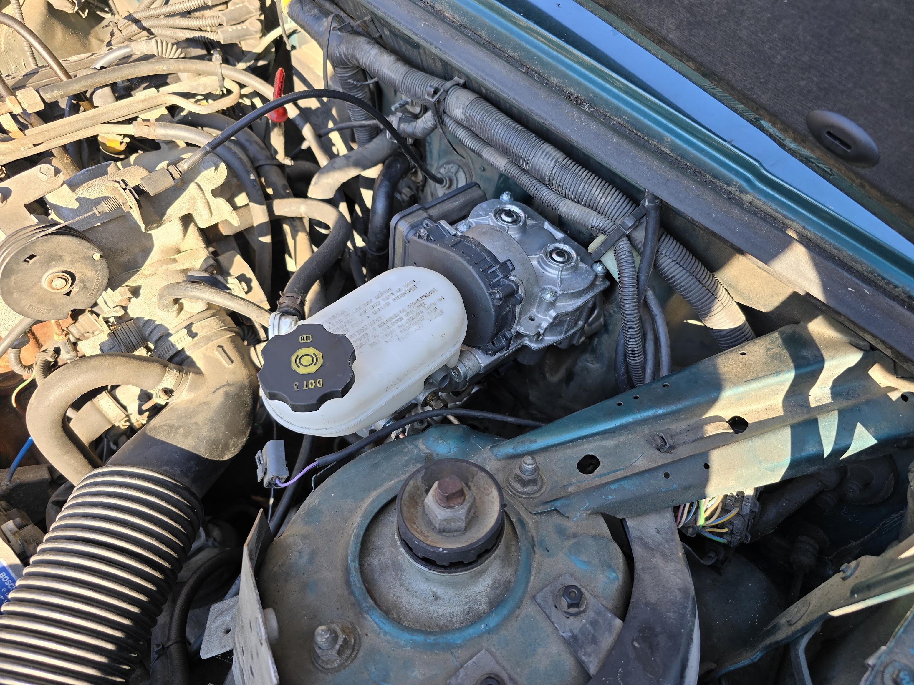 iBooster installed in the Volvo. Looks almost original!
The orignal brake lines weren’t in the right spot due to the master cylinder on the iBooster having the ports on a different side, but after running new copper brake lines to the small distribution-looking block underneath the cylinder, bleeding the brakes and hooking up power, the brakes work normally!
One minor complication with this retrofit is that the clutch was also operated hydraulically with brake fluid from the same reservoir, so we had to add an small extra tank (the iBooster master cylinder tank doesn’t have a port for this).
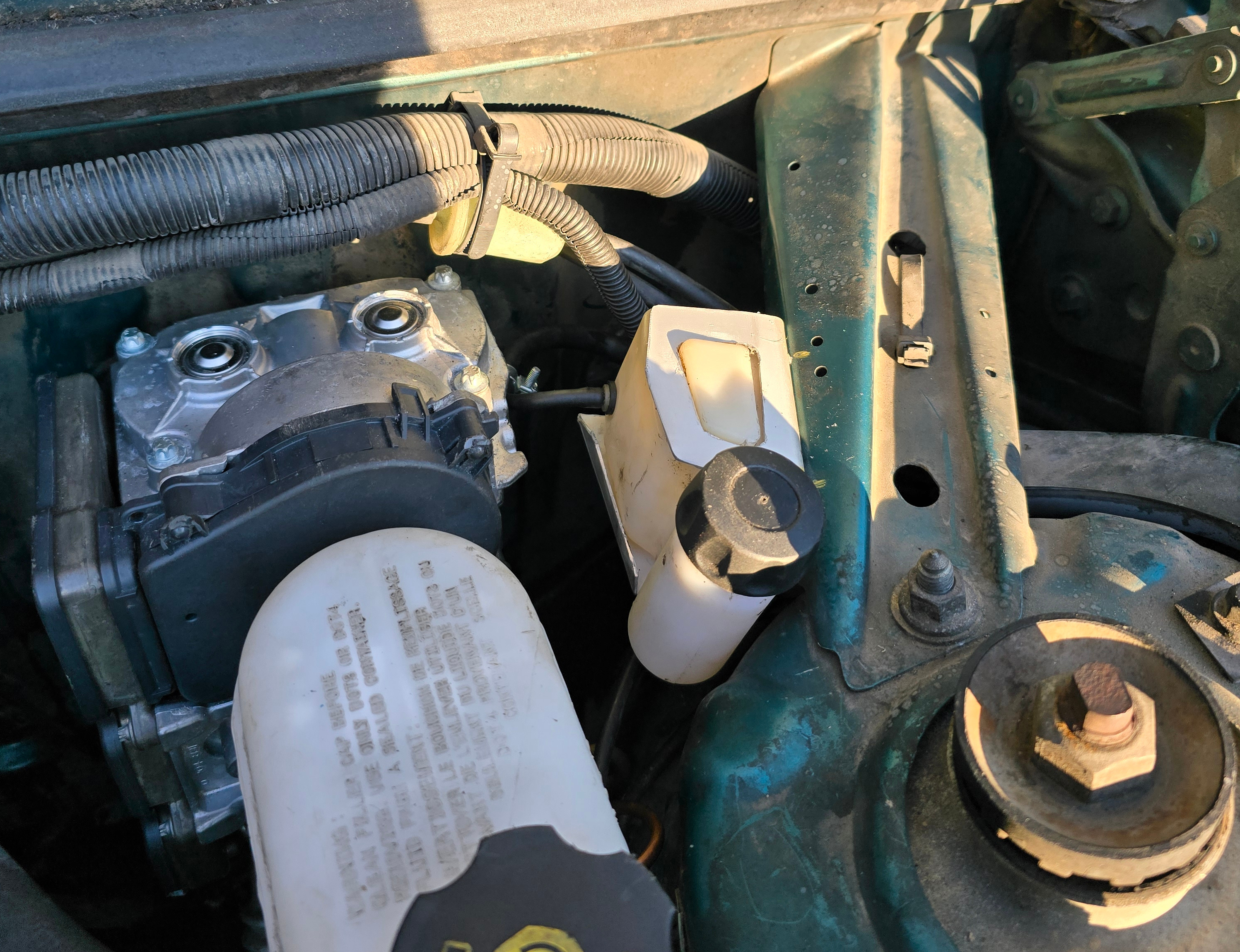 Small tank with brake fluid for the clutch
Accelerator servo
Sometimes you also want to go faster instead of slower! Another thing that Volvo implemented purely mechanically.
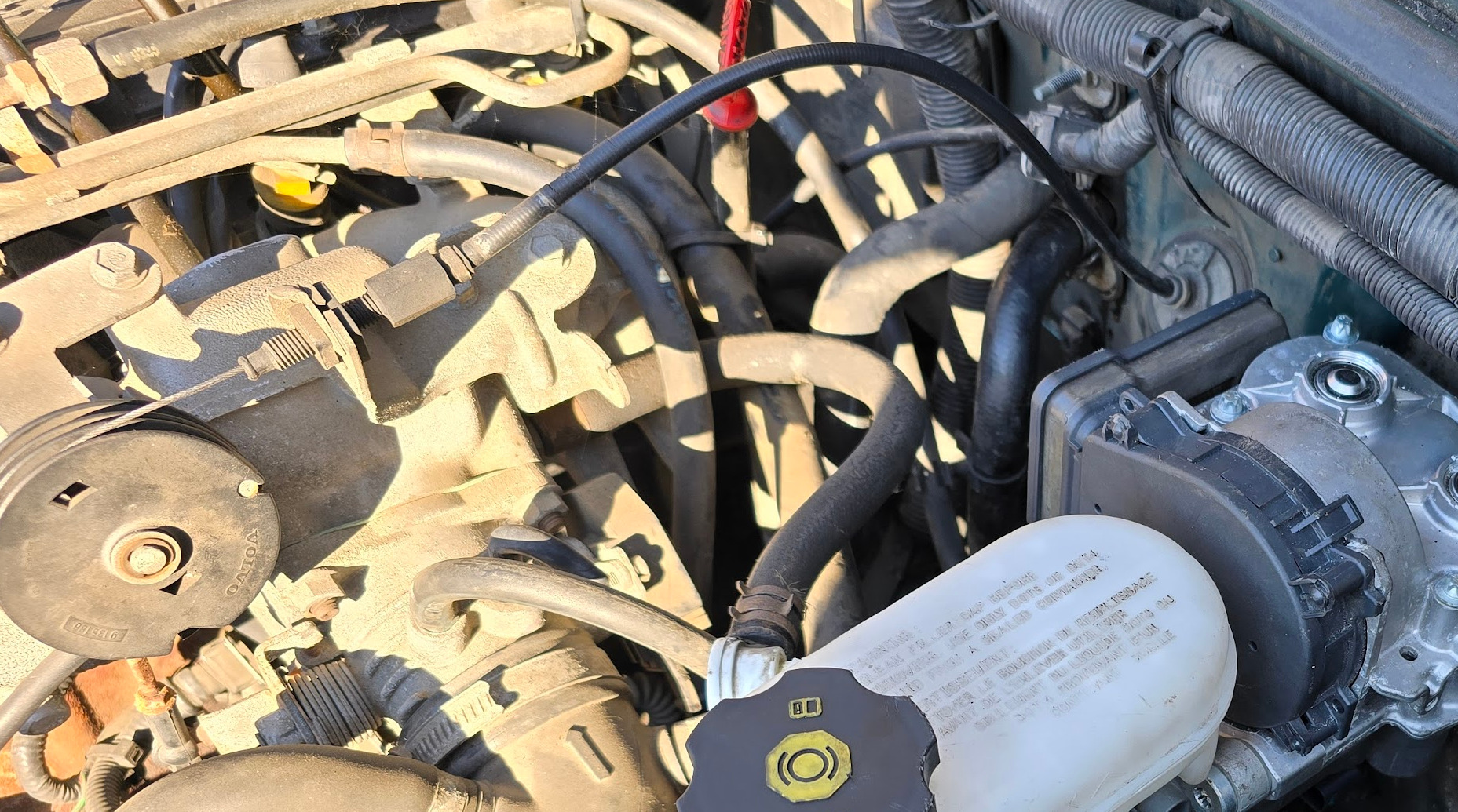 The accelerator pedal is connected to the carburator air valve by means of a bowden cable
This is the only major actuator that I couldn’t easily find a suitable modern automotive solution for. This is mainly because newer cars don’t have carburators anymore, but rather use direct injection and advanced engine control units. Luckily this is also the only actuator that doesn’t come with major safety implications, so let’s just hack something together with off-the-shelf hobby parts!
Standard cruise control logic dictates that the driver can override the applied accelerator position by just pressing harder on the accelerator pedal himself. This is easy enough to implement by just having two cables connected to the air valve pulley: the cable that pulls the furthest wins.
With this in mind, I bought a (surprisingly strong!) waterproof RC servo from AliExpress, and had my Dad machine a second pulley that mounts onto it. After that it was just a matter of cobbling together a mount for the servo, and adding some bronze guide bushings to constrain the loose cables, and we’re in business!
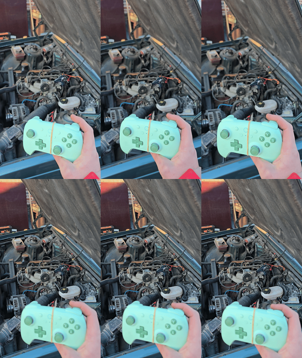 Vroom vroom!
Bonus content!
While this isn’t an actuator, we also fitted a Tesla Continental radar sensor behind the front grille. While vision-only ACC somewhat works in openpilot, being able to rely on a real radar still makes for a smoother and more consistent experience.
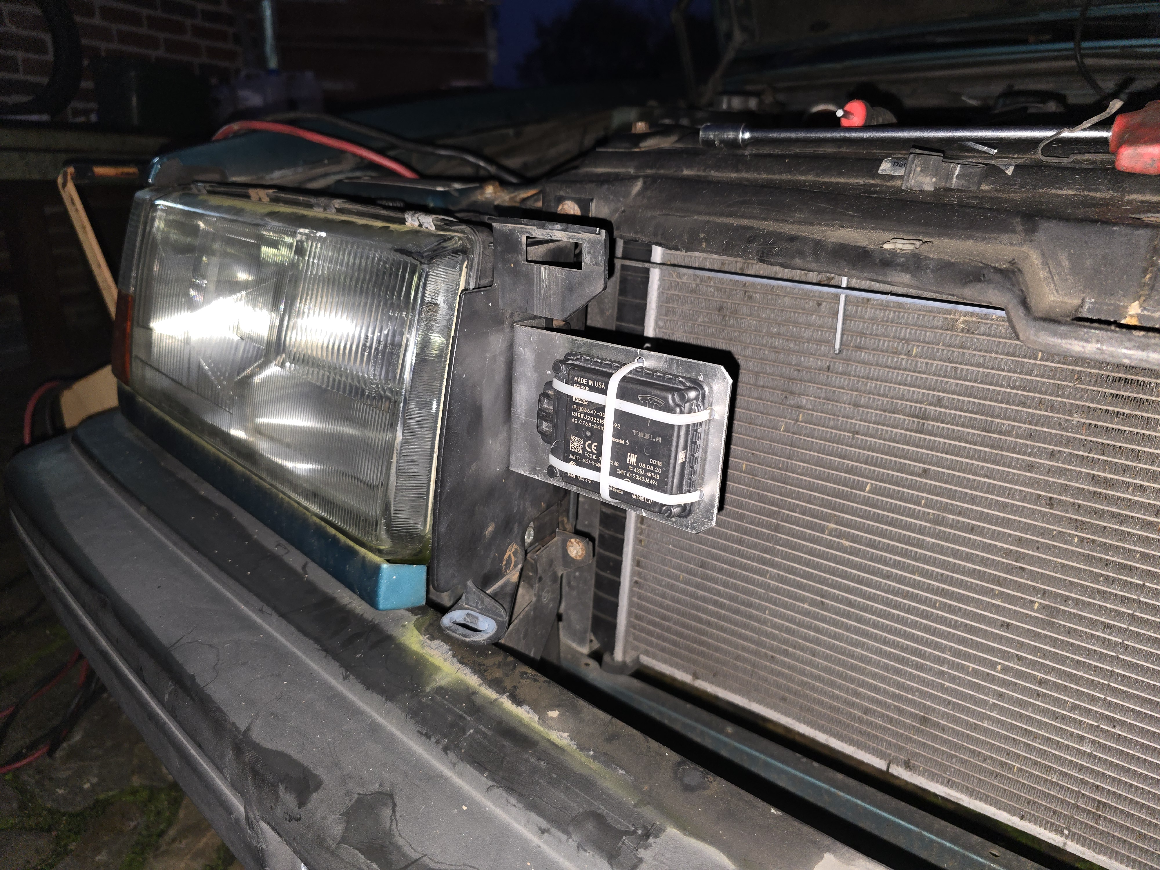 Ping Ping!
Wow what an amazing blog post!!! When will part 2 come out??
Good question. I’m lazy, so it might take a while. On the other hand, we’ll have tons of time in the car in a few weeks, so maybe then?
I think part 2 will be about the wiring and the custom ECU I designed to keep the actuators happy, and to implement things like the cruise control buttons, as well as reading out the speed, blinkers, …
After that, I’ll do part 3 explaining (and open sourcing) the code on the ECU and the openpilot port.
After that, who knows! What would you like me to talk about more?