A few months ago, I decided that it’s time I started to become more responsible and to start drinking more water. Unfortunately, the tap water where I live has a very high calcium content, which makes it a lot better when filtered and cooled first. To solve both issues, I picked up a second-hand professional water dispenser:
 ION 900 series water dispenser
This thing is amazing. It’s connected to the water supply, has power save features when it detects it’s in the dark for a while, the filter lasts for years, …
Along with the cooler, I also bought thermally-isolated 1L bottles, which take about 50 seconds to fill. Unfortunately, you have to keep pressing the “dispense cold water”-button while filling 😑.
Since I’m lazy and not very rational in my decision making, I decided it’s time to fix that!
What makes it tick?
It’s pretty simple! The main part of the cooler is an insulated vat of chilled water (cooled by a compressor like in a fridge), through which the stainless steel tube of fresh filtered water flows:
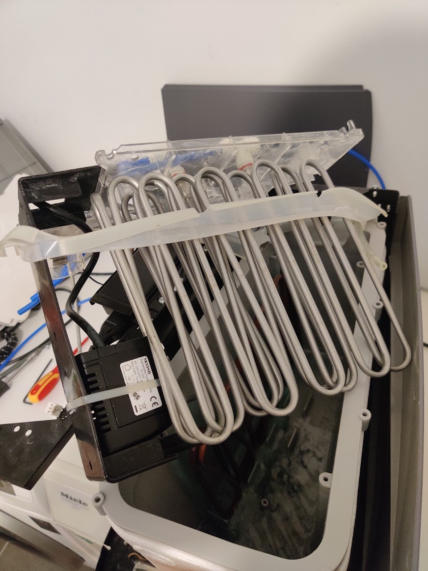
Water vat with the insulation removed
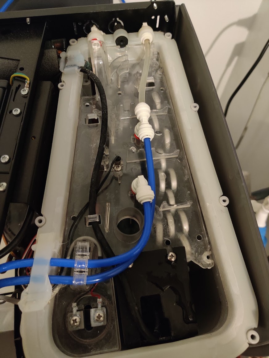
To control the water flow, it contains multiple 24VDC valves. Other than that, the cooler contains some temperature sensors, a stirring pump, a fan, …
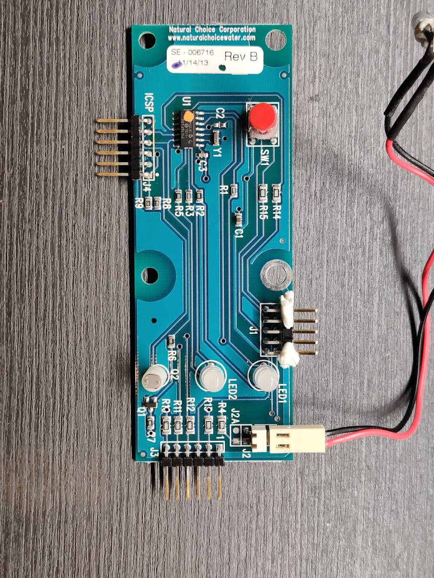
This all is controlled by the main PCB, containing an 8-bit PIC18F6527 microcontroller. In the front panel, there’s another PCB with a PIC16F630 to handle the LEDs and light sensor.
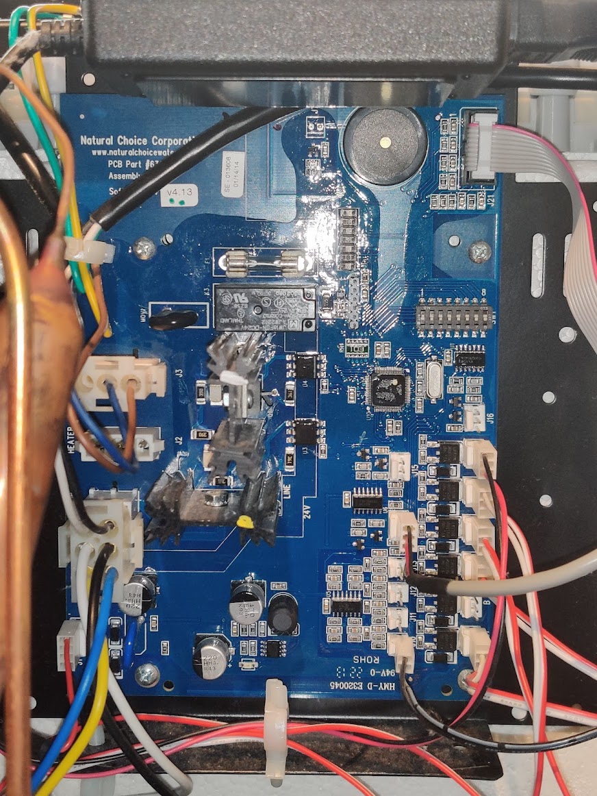
The two PCBs in the water dispenser
Dumping the binary
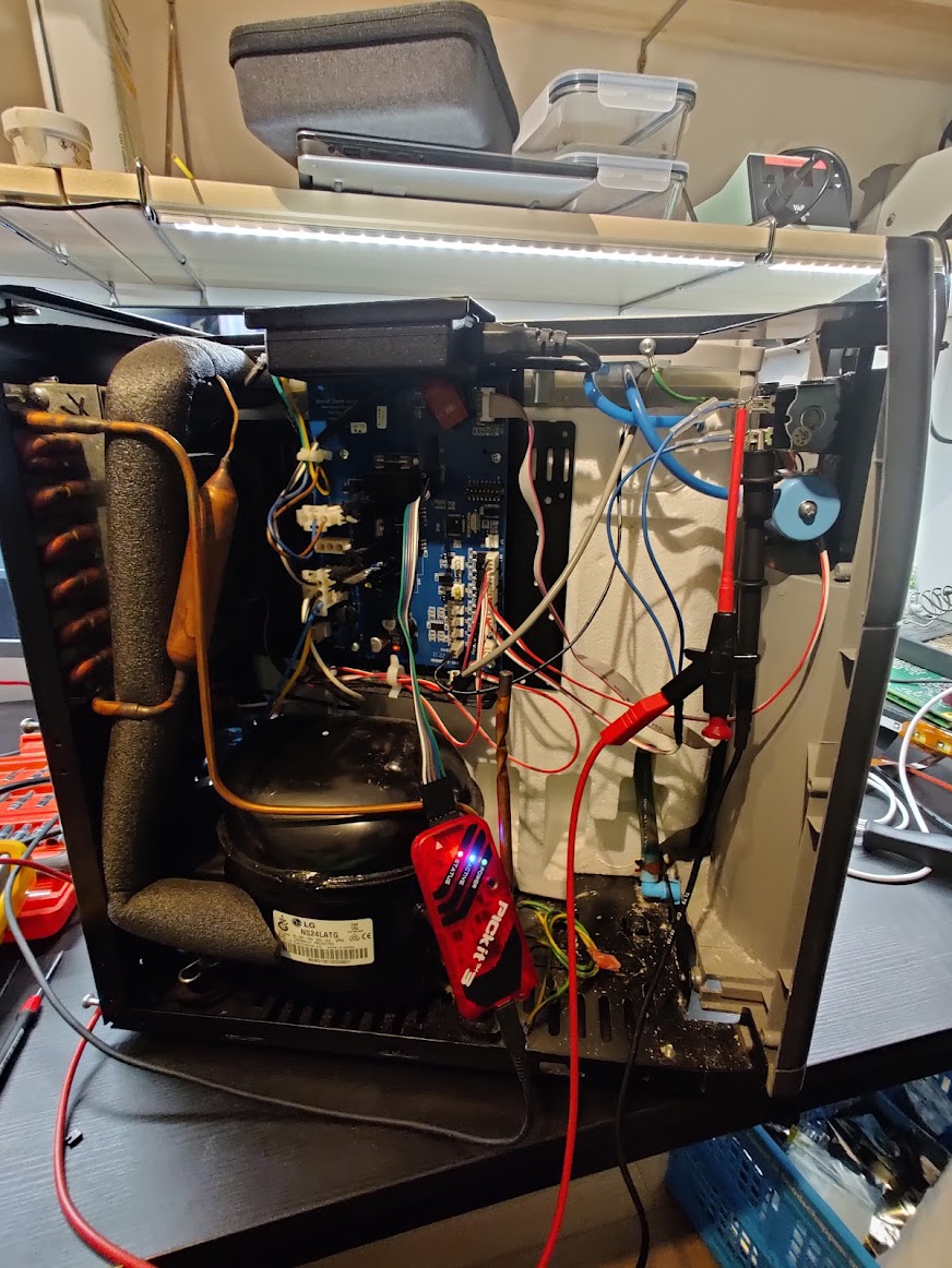
To modify the code running on the microcontrollers, we first have to get our hands on a copy of the binary. Keen-eyed readers might have already spotted the ICSP headers on both PCBs, which can be connected directly to a PICkit in-circuit programmer!
When starting this project, my PICkit was still on order, so I implemented a dumper based on the ICSP logic of the PIC-18 by using an Arduino:
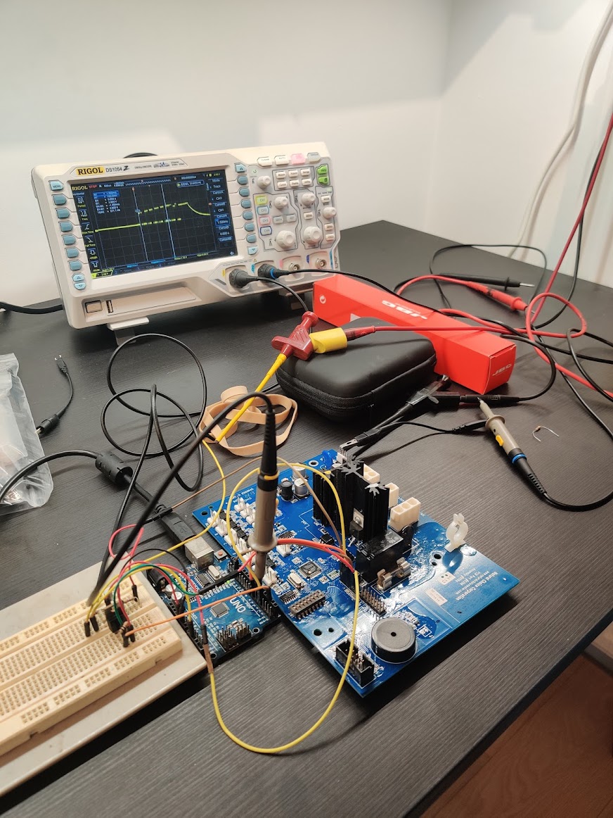 Arduino PIC dumping setup, with external MOSFET to power the board
The resulting dumps can be found in the public GitHub repo of this project here.
Reverse engineering the firmware
To be able to implement a new feature in this firmware, we first need to have an idea of what that binary is actually doing. Of course, having the binary doesn’t give you the source code,
but by disassembling it you get the assembly instructions and can even get an approximate version of the source code that might have produced this assembly.
For this, I used Ghidra, a tool developed and open-sourced by the NSA. Luckily, Ghidra already supports the PIC-18 architecture. Opening up the binary and running all the standard analysis tool, the project contains a lot of detected functions which look a bit like this:
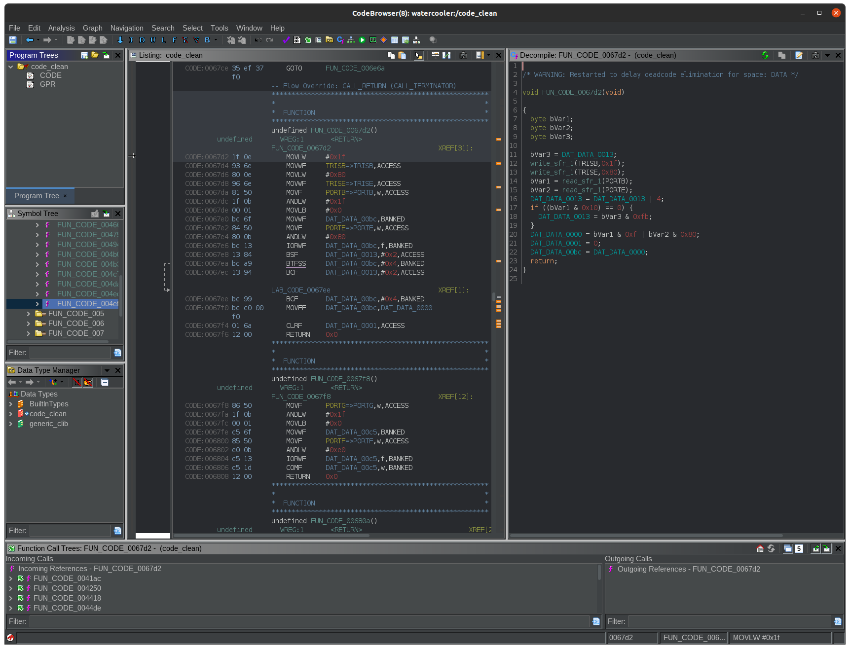
On the left hand side of the screen, the binary data and disassembled instructions are shown, while on the right Ghidra has done it’s best decompilation effort:
void FUN_CODE_0067d2(void) {
  byte bVar1;
  byte bVar2;
  byte bVar3;

  bVar3 = DAT_DATA_0013;
  write_sfr_1(TRISB,0x1f);
  write_sfr_1(TRISE,0x80);
  bVar1 = read_sfr_1(PORTB);
  bVar2 = read_sfr_1(PORTE);
  DAT_DATA_0013 = DAT_DATA_0013 | 4;
  if ((bVar1 & 0x10) == 0) {
    DAT_DATA_0013 = bVar3 & 0xfb;
  }
  DAT_DATA_0000 = bVar1 & 0xf | bVar2 & 0x80;
  DAT_DATA_0001 = 0;
  DAT_DATA_00bc = DAT_DATA_0000;
  return;
}
Since no debug symbols are present in this binary, all variables and functions have been given generic names like FUN_CODE_0067d2, DAT_DATA_0013 and bVar3. Let’s explain a bit what these refer to:
FUN_CODE_0067d2: This is a generated label referring to the detected function at address0x67d2. Since the PIC18 is based on the Harvard architecture with separate instruction an data memory spaces, Ghidra denotes this address asCODE_0067d2since it’s in theCODEmemory space.DAT_DATA_0013: This label denotes a 8-bit data variable located in theDATAmemory space at address0x0013. The CPU in the PIC18 does not have general-purpose registers (except forWREG), so it uses variables stored in data memory for most of its computations and function arguments. Since it re-uses most of these addresses so often, it’s really annoying to annotate the global variables used in the reverse engineered code.bVar3: This denotes byte-sized variable number 3, used locally. Variables like these are inserted in the decompilation, but are not actually represented in the data memory anywhere.
Looking at what this decompiled code of this function is doing, we can see that it sets the TRISB and TRISE registers, after which it reads out PORTB and PORTE and does some processing with it. Referencing the PIC18F6527 datasheet, we can see that this sets the direction of the GPIO port B and E pins, after which it reads the values.
Using this knowledge, we can rename the labels used in the code and add some comments to make it a bit more readable:
void read_port_b_e(void) {
  byte port_b_value;
  byte port_e_value;
  byte tmp_flag;

  tmp_flag = DAT_DATA_0013;

  // Set certain port B and E pins as input
  write_sfr_1(TRISB,0x1f);
  write_sfr_1(TRISE,0x80);

  // Read the value of the ports
  port_b_value = read_sfr_1(PORTB);
  port_e_value = read_sfr_1(PORTE);

  // If pin B4 is low, clear a flag in `DAT_DATA_0013`
  DAT_DATA_0013 = DAT_DATA_0013 | 4;
  if ((port_b_value & 0x10) == 0) {
    DAT_DATA_0013 = tmp_flag & 0xfb;
  }

  // DAT_DATA_0000 is the return value used by the calling functions
  DAT_DATA_0000 = port_b_value & 0xf | port_e_value & 0x80;
  DAT_DATA_0001 = 0;
  DAT_DATA_00bc = DAT_DATA_0000;
  return;
}
By tracing the buttons on the front panel to the PIC on the main PCB, we find following connections:
- Pin
B0: Room temperature water dispense - Pin
B1: Cold water dispense
We also find that this is the only function in the binary to reference PORTB, which makes us sure that this is the function which will be called to check the status of the front panel buttons.
Using this process, I decompiled and found most of the functions we’re interested in, under which for example:
beep()at0x7118: Like the name suggests, calling this function with the desired duration inDAT_DATA_0000(LSB) andDAT_DATA_0001(MSB) makes the beeper beep!delay()at0x75c8: Regular delay function, with the desired duration inDAT_DATA_0000(LSB) andDAT_DATA_0001(MSB)close_all_valves()at0x62e8: Closes all dispensing valvesdispense_cold_water()at0x6332: Opens the inlet valve and the cold water dispensing valvehandle_button_presses_and_dispense()at0x639c: This function is called in the main program loop and checks the button state throughread_port_b_eand calls the appropriate dispensing functions.
The Ghidra project with all the labels I added can be found here.
Strategy
Ok, time to get our hands dirty and let’s see how we can add the hands-free functionality we want.
After some consideration, I settled on the following simple patches:
- Replace the call to
read_port_b_e()in thehandle_button_presses_and_dispense-function with a call to my ownpatchfunction - Have
patch()callread_port_b_e(), and with the returned “actual” button states perform the added function - Return a “faked” button state based on this added logic
Building a patch (C code)
I don’t like writing assembly, especially in cases like this when there is some trial-and-error going on. Instead, I opted to download Microchip’s XC8 compiler and use it to compile the binary patches straight from C code.
In the end, I settled on this code:
// This is a patch to have a predefined amount of cold water
// dispensed when you press the "room temp water" button
// while holding the "cold temp water" button

// It hooks into the `dispense_room_temp_water()` function (since that's called first)
// and loops there for a predefined delay if there's also cold water dispensing.

#include <xc.h>
#include <stdint.h>
#include <proc/pic18f6527.h>

// Used pointers in the original code:
volatile uint8_t *return_val_ptr = (volatile uint8_t *)0x0000;
volatile uint8_t *beep_time_L_ptr = (volatile uint8_t *)0x00be;
volatile uint8_t *beep_time_H_ptr = (volatile uint8_t *)0x00bf;

extern void read_port_b_e(void) __at(0x67d2);
extern void beep(void) __at(0x7118);

// Globals
uint32_t fake_dispensing_counter;
uint8_t handsfree;

#define INIT_MAGIC 0xA5A5
volatile uint16_t init_checker;

// Put the patch function at a known empty address
// to make it easy to find in the binary
void patch() __at(0x8000);
void patch() {
  // We wrap the button readout function to be able to fake button presses
  // in the dispensing logic.

  // Init variables if not done so already.
  // Since this is in RAM, everything will have an unknown value at startup
  if (init_checker != INIT_MAGIC) {
    fake_dispensing_counter = 0;
    handsfree = 0;
    init_checker = INIT_MAGIC;
  }

  // Read real status
  read_port_b_e();

  if (fake_dispensing_counter == 0 && ((*return_val_ptr) & 0x3) == 0x3) {
    // Pressing both buttons, so we start the fake dispense and beep.
    // This will dispense about 1L
    fake_dispensing_counter = 0x20000;
    handsfree = 0U;

    *beep_time_L_ptr = (uint8_t) 0x05;
    *beep_time_H_ptr = (uint8_t) 0x01;
    beep();
  }

  if (fake_dispensing_counter > 0) {
    if ((handsfree == 0) && (((*return_val_ptr) & 0x3) == 0)) {
      // We released the buttons
      handsfree = 1U;
    }

    if ((handsfree != 0U) && (((*return_val_ptr) & 0x3) != 0)) {
      // We cancelled by pressing a button
      *beep_time_L_ptr = (uint8_t) 0x05;
      *beep_time_H_ptr = (uint8_t) 0x00;
      beep();

      fake_dispensing_counter = 0U;
      return;
    }

    // Fake only cold water button
    *return_val_ptr = ((*return_val_ptr & 0xf0) | (1 << 1));

    fake_dispensing_counter--;
  }
}

// xc8 does not generate .o files, so we need to have main()
void main() __at(0x10);
void main() {
  patch();
}
While writing and compiling something like this, there are a few caveats we need to be aware of, and work around.
First of all, there’s the issue that the functions will be packed into the smallest binary possible, with the function addresses being close to 0x0000. To address this (pun intended), we added the __at(<address>) directives to force the compiler to put the code in a certain memory location. Since the original code stops at 0x7692, 0x8000 seemed like a nice spot to put our patch().
Second issue we encounter is that we have to make the compiler aware to stay clear of the DATA variables used by the original code. In Ghidra, we can see that the original code only uses DATA variables with addresses below 0x100, hence we call the compiler with the argument to reserve that area. This option is intended to be used for code that’s used with bootloaders, but comes in handy in our specific case as well. We invoke the compiler as such:
xc8-cc -mcpu=pic18f6527 -opt=none -mram=default,-0000-0100 -o out/hook hook.cFinally, we need to be aware that we can’t rely on the global variables to be initialized with a known value. Initializing it globally in this code would result in the compiler generating some instructions to be run before main() is called, which we can’t very easily patch into the original binary. A more simple way was used, namely by dedicating a global uint16_t as a flag with a magic value to check the initialization status.
Let’s look at the generated binary
Opening up and analyzing the freshly compiled hook binary in Ghidra, we can see that our code is indeed in the intended locations, and that it only uses DATA variables over 0x100, except when needed as arguments or return values. This is the decompiled version of the patch() function:
byte FUN_CODE_008000(void)

{
  bool bVar1;
  byte bVar2;
  bool bVar3;

  if ((DAT_DATA_0105 != -0x5b) || (bVar2 = DAT_DATA_0106 ^ 0xa5, bVar2 != 0)) {
    DAT_DATA_0101 = 0;
    DAT_DATA_0102 = 0;
    DAT_DATA_0103 = 0;
    DAT_DATA_0104 = 0;
    DAT_DATA_0109 = '\0';
    DAT_DATA_0106 = 0xa5;
    bVar2 = 0xa5;
    DAT_DATA_0105 = -0x5b;
  }
  func_0x0067d2(bVar2);
  if (((DAT_DATA_0104 | DAT_DATA_0103 | DAT_DATA_0102 | DAT_DATA_0101) == 0) &&
     ((bDATA0000 & 3) == 3)) {
    DAT_DATA_0101 = 0;
    DAT_DATA_0102 = 0;
    DAT_DATA_0103 = 2;
    DAT_DATA_0104 = 0;
    DAT_DATA_0109 = '\0';
    DAT_DATA_00be = 5;
    DAT_DATA_00bf = 1;
    func_0x007118();
  }
  bVar2 = DAT_DATA_0104 | DAT_DATA_0103 | DAT_DATA_0102 | DAT_DATA_0101;
  if (bVar2 != 0) {
    if ((DAT_DATA_0109 == '\0') && (bDATA010e = bDATA0000 & 3, bDATA010e == 0)) {
      DAT_DATA_0109 = '\x01';
    }
    if ((DAT_DATA_0109 == '\0') || (bDATA010e = bDATA0000 & 3, bDATA010e == 0)) {
      bDATA0000 = bDATA0000 & 0xf0 | 2;
      bVar3 = DAT_DATA_0101 != 0;
      DAT_DATA_0101 = DAT_DATA_0101 - 1;
      bVar2 = 0;
      bVar1 = DAT_DATA_0102 != ~bVar3;
      DAT_DATA_0102 = DAT_DATA_0102 - ~bVar3;
      bVar3 = DAT_DATA_0103 != ~bVar1;
      DAT_DATA_0103 = DAT_DATA_0103 - ~bVar1;
      DAT_DATA_0104 = DAT_DATA_0104 - ~bVar3;
    }
    else {
      DAT_DATA_00be = 5;
      DAT_DATA_00bf = 0;
      func_0x007118();
      DAT_DATA_0101 = 0;
      DAT_DATA_0102 = 0;
      DAT_DATA_0103 = 0;
      bVar2 = 0;
      DAT_DATA_0104 = 0;
    }
  }
  return bVar2;
}
Patching the original binary
Now that we have a binary version of the patch(), we can just copy that part of the binary over to the original code at address 0x8000.
After this, there’s only one thing left: replacing the call in handle_button_presses_and_dispense() from read_port_b_e() at 0x67d2 to the new patch() function at 0x8000.
To do this, we could do this by hand by recalculating and replacing the argument bytes in the CALL-instruction, but Ghidra has a nice feature for this! Right-clicking on the instruction you want to patch and selecting ‘Patch Instruction’ allows you to edit the assembly line directly, and it’ll automagically recalculate the binary representation. How awesome!
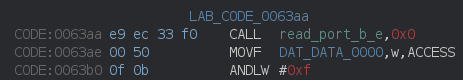
Original CALL-instruction
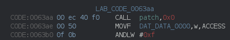
Patched CALL-instruction
Export the binary from the Ghidra project, convert it to the right Intel HEX format used by Microchip IPE and we’re ready to flash! By now my PICkit had arrived, which made easy work of flashing.
 I had a proper PICkit for flashing now!
Results and conclusions!
Et voila! A working patch for hands-free mode, complete with cancel functionality and annoying beeps!
Added hands-free dispensing! Can even cancel the pour mid-way by pressing a button again.
— Robbe Derks (@robbederks) December 21, 2021
Timer needs some tweaking to fill my bottle, but this will definitely save me 30s of button pressing a day! pic.twitter.com/90bHw7xXmo
In the end, it took about 8 hours to get this project finished, which was spread out over multiple weeks. Considering that I usually fill my bottle once a day, and it takes about 50 seconds to do so, this will have a positive return-on-investment after only about 1.5 years!